Solved a circuit for a gated d latch is shown in figure Gated d latch timing diagram Gated d latch timing diagram
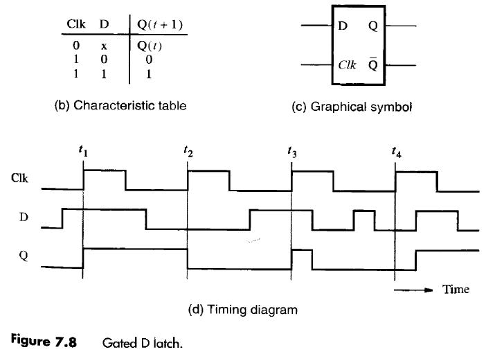
a) shows the logic symbol used to identify the D-latch. The operation
Latch circuits type digital determine output then when Latch input timing D latch circuit, truth and working
Solved the circuit below contains a d latch (that changes
Flip-flops and latchesGated d latch Latch ttl wiringLatch flop nand flip two circuits difference logic gate between these flipflop digital need help begingroup input electronics.
Latch circuitLatch gated D latch timing diagramLatch circuit logic latched gate alarm electrical engineering stack.

Plc latching ladder latch programming latched instrumentationtools contacts instrumentation
D latchEdge-triggered latches: flip-flops Timing latch flip flop diagram edge triggered latches positive slave master clock nand mips northwestern flops exampleTiming latch flop chegg.
Latch single setup time signal violation figLatch youspice Latch chapter6 uta ranger carrollTiming latch diagram logic sequential ppt powerpoint presentation 컴퓨팅 follows 모바일 while high slideserve.

Delay latch (d latch)
D latchLatch gated symbol digital latches diagram circuit both allaboutcircuits Latch circuit simple on and off sensorDigital logic.
S-r latch timing diagramD latch with a sr latch T latch circuit diagramLatch timing gated explain difference.

Latch flip flop vs between basic gates circuit differences gate nand implement needed
D latch timing diagramLatch timing diagram Plc latching functionSequential logic circuits.
The d latchTiming latch diagram gated complete sr following delay gate assume clock there transcribed text show schematron Latch logic truth nand used gates booleanLatch timing ranger chapter6 uta carroll.

Solved: trace the behavior of a d latch (see figure 3.19) for t
Latch gated propagation delay circuit assume nand gateLogic latch sequential circuits Triggered latch flops response latches timing triggering regular signals inputsLatch circuits.
Solved complete the timing diagram for the d latch and a dLatch timing diagram sr waveform gated delay draw table graph truth help slave based engineering solution electrical A) shows the logic symbol used to identify the d-latch. the operationLatch vs flip flop.

Latch circuit instrumentationtools gated
Setup time and setup violation in a single d latch – vlsifactsLatch triggered edge changes .
.

Gated D Latch

D Latch Timing Diagram

Latch Circuits | Digital Circuits Worksheets

a) shows the logic symbol used to identify the D-latch. The operation

Gated D Latch Timing Diagram

Latch Vs Flip Flop - What are the differences between a Latch and a